The Vanguard
DIY stomp box Bass preamp

So, just as most guitar players have their pedalboards, so do bass guitar players. My personal pedalboard has gone through a massive change the last 6 month or so, which led to a practical problem.
As I started using stereo effect pedals, I ran into a "connectivity" problem. I wanted to split the signal into two different signal paths, one dry (none modulated) and one wet (modulated), and then mix them together. This is called paralell processing and is quite common these days. The main benefit of this is that your clean (dry) signal is kept as clean as possible, while the effected signal (wet) goes a signal path of its own, and then the two signal paths is then mixed together in the audio mixer. Especially when using stereo effect pedals as delays, reverbs, choruses etc. you end up with the left effect signal in the left side, mono dry in the middle, and the right effect signal in the right side. Also known as a wet-dry-wet configuration.
However, this caused me with a connectivity problem, since the bass preamp pedal I had only had one single (mono) output.
So, time to design a new bass preamp pedal for my specific needs. One mono input, adjustable gain (just in case I'll one day need it), three band EQ (Bass, Mid, Treble) and a active adjustable high-pass filter to remove the lows that would be fed into the wet signal path, with two outputs (dual mono).
The preamp and EQ section was the easy part, I had already designed and built several 3-band onboard preamps for my basses, like "The Seven Seas".
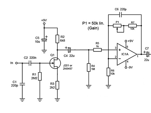
So to get that adjustable gain I just had to connect a pot in series with R4, and change the value of R3 and R4 to 10kohm to get unity gain when no gain is added by the pot. I also wanted to make a JFET input stage to get a bit more tube-like sound. So this is what I ended up with.

The JFET stage provides a high input impedance and boosts the signal by 9dB, while IC1A have a adjustable boost of 0-17dB. So now I needed a active high-pass filter. Never even seen a schematic of one so this project was getting interesting. Searched the net for schematics and found one that looked fairly simple. U1A works just as a input buffer so I removed that and breadboarded the circuit. Seemed to work just fine, however the highest x-over frequency was about 200Hz. I wanted it to be a bit higher so I changed the values of C1 and C2 from 150nF to 100nF which raised the max x-over frequency to about 300Hz.

While I was searching the net for this high-pass filter circuit I also stumbled across a neat little op-amp circuit that was an adjustable clip LED circuit. This was very convenient since I ended up with one spare op-amp from this high-pass circuit.

So what I ended up with was;
| - True JFET mono input |
| - Adjustable gain (0 - +17dB) |
| - 3-band active EQ (Bass, Mid, Treble) |
| - Dry mono output (Output A) |
| - Dual mono outputs with adjustable HPF (Output B and C) |
| - Clip (overload) LED |
Below a schematic of the whole thing;

For the enclosure I chose the Hammond 1590N1, a slightly bigger die cast aluminum enclosure than the popular 1590B. With five pots, four 1/4" input/output sockets, two circuit boards and all those cables in there, it got very crowded very quickly. I never been too fond of making etched circuit boards, so these days I use perfboard with those "dots" of copper foil around each hole. Makes soldering fairly easy as opposed to those perfboards without copper foil.

For this project I wanted to try out something different than just spray paint. So I got this idea of brushing so sort of pattern onto the enclosures clean aluminum surface with a small circular brass brush on a rotary tool.

So all that was left to do was printing out those waterslide label decals, position them and finally a few coats of matte spray laquer. Time for some tedious soldering and cable management and it started looking like an effect pedal.

